Lecture 23 – Designing a datapath (continued): Difference between revisions
m (Mike moved page Lecture 22 – Designing a datapath (continued) to Lecture 23 – Designing a datapath (continued)) |
|
(No difference)
| |
Latest revision as of 15:58, 17 July 2022
This lecture continues the story begun in the previous lecture. We rearrange the datapath slightly, and add more elements that implement a bigger subset of the Thumb instruction set. The theme shifts slightly from providing the datapath elements needed to perform operations on data to implementing the control elements concerned with the detail of decoding instructions and controlling the flow of execution, including conditional branches and subroutine calls.
Stage 6: PC as a register
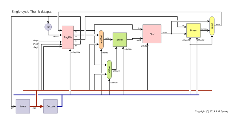
Up to now, we have kept the PC separate from the general register files, as indeed it is on some architectures. But on the ARM, the PC can be accessed like other registers, and used in PC-relative addressing. So our next step is to merge the PC into the register file, using a design for a 'turbocharged' register file we prepared earlier.
In addition to the three selectable outputs that can output the value of any register (including the PC), there is now a special-purpose output that always carries the (current) PC value. There is also a separate input that receives the value of PC+2, which will be written to the PC if it is not specifically selected for the writing of a different value: this allows for the implementation of branch instructions at a later point. We'll assume that the design of the register file includes an adjustment so that, when the PC is read as an ordinary register, the specified value PC+4 is output.
Stage 7: Instruction decoding
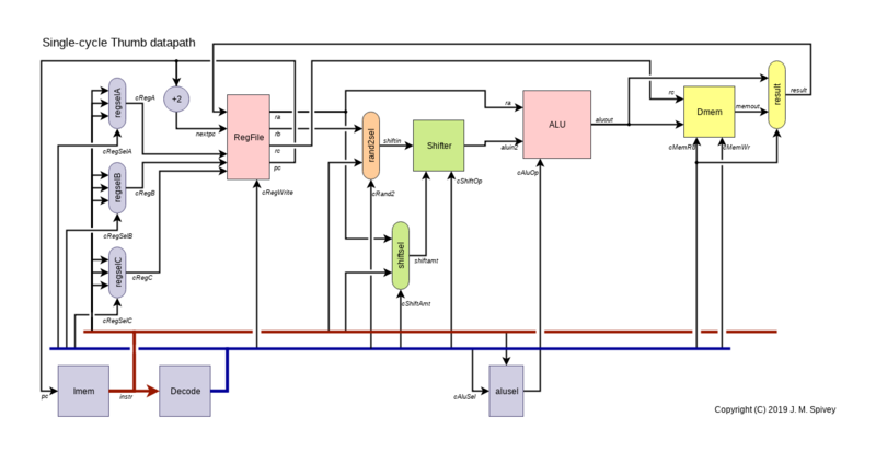
We've got quite a good table of control signals now, so it's time to fill in more details of the decoding process. Each instruction uses up to three registers, sometimes selected by fields in the instruction, and sometimes fixed as SP or LR or PC. To sort this out, we can add three identical multiplexers, driven by control signals cRegSelA, cRegSelB, cRegSelC, that either select one of a list of fields (Rx, Ry, Rz, Rw) from the instruction or give a fixed value (Rsp, Rlr, Rpc).
The other addition in this figure is a unit called alusel. This tidies up a couple of instructions where the ALU operation could be add or subtract, but the decision is not determined by the first few bits of the instruction. One pair of such instructions are the ones that add or subtract a constant from the stack pointer, using instr<7> to decide which.
The other such pair are the forms add/sub r/i3 shown earlier that use bit instr<10> to decide whether the second operand is a register or a 3-bit immediate field, and use instr<9> to decide between adding and subtracting. The alusel decoder sorts out the details, and the details can be found in the code of the simulator.
Let's refresh the table of control signals, adding the three register selectors, and also adding at the left a column that shows the leftmost bits of the instruction, always bits instr<15:11> and sometimes further bits. We'll do that for our selection of example instructions first.
| Instruction | opcode | cRegSelA |
cRegSelB |
cRegSelC |
cRand2 |
cShiftOp |
cShiftAmt |
cAluSel |
cMemRd | cMemWr | cRegWrite |
|---|---|---|---|---|---|---|---|---|---|---|---|
adds/subs r/i3 |
00011 | Ry |
Rz |
Rx |
RImm3 |
Lsl |
Sh0 |
Sg9 |
F |
F |
T
|
movs i8 |
00100 | - | - | Rw |
Imm8 |
Lsl |
Sh0 |
Mov |
F |
F |
T
|
ldr r |
01011 | Ry |
Rz |
Rx |
RegB |
Lsl |
Sh0 |
Add |
T |
F |
T
|
str r |
01010 | Ry |
Rz |
Rx |
RegB |
Lsl |
Sh0 |
Add |
F |
T |
F
|
lsls i5 |
00000 | - | Ry |
Rx |
RegB |
Lsl |
ShImm |
Mov |
F |
F |
T
|
ands r |
01000:00000 | Rx |
Ry |
Rx |
RegB |
Lsl |
Sh0 |
And |
F |
F |
T
|
rors r |
01000:00111 | Ry |
Rx |
Rx |
RegB |
Ror |
ShReg |
Mov |
F |
F |
T
|
ldr i5 |
01101 | Ry |
- | Rx |
Imm5 |
Lsl |
Sh2 |
Add |
T |
F |
T
|
str i5 |
01100 | Ry |
- | Rx |
Imm5 |
Lsl |
Sh2 |
Add |
F |
T |
F
|
This is a fair selection of instructions for the machine, especially if we let ands stand as an example of register-to-register ALU operations and rors stand as an example of shifts with the shift amount taken from a register. Most instructions can be identified from their first five bits and set out in a table of 32 possibilities. Among those implemented in the simulator, most of the rest start with 010000 or 010001, and can be identified using two further, smaller tables. All these tables could become ROMs in a hardware implementation. This part of a Thumb implementation is more complicated than is typical for RISC machines because of the variety of instruction formats. For comparison, the MIPS has just three instruction formats, all 32 bits long: one that names three registers, one that has two registers and a 16-bit immediate field, and a third format with a large offset for subroutine calls.
The datapath as it stands also contains the resources to implement a number of other instructions. For example, there is are several instructions that implicitly involve the stack pointer, including the two shown above, an instruction that forms an address by adding a constant and the stack pointer, and instructions that load and store from that address.
All of these can be implemented using the register selector Rsp:
| Instruction | opcode | cRegSelA |
cRegSelB |
cRegSelC |
cRand2 |
cShiftOp |
cShiftAmt |
cAluSel |
cMemRd | cMemWr | cRegWrite |
|---|---|---|---|---|---|---|---|---|---|---|---|
add/sub sp |
10110 | Rsp |
- | Rsp |
Imm7 |
Lsl |
Sh2 |
Sg7 |
F |
F |
T
|
add rsp |
10101 | Rsp |
- | Rw |
Imm8 |
Lsl |
Sh2 |
Add |
F |
F |
T
|
ldr sp |
10011 | Rsp |
- | Rw |
Imm8 |
Lsl |
Sh2 |
Add |
T |
F |
T
|
str sp |
10010 | Rsp |
- | Rw |
Imm8 |
Lsl |
Sh2 |
Add |
F |
T |
F
|
We can also implement unconditional branches that add a signed 11-bit constant to the PC.
| Instruction | opcode | cRegSelA |
cRegSelB |
cRegSelC |
cRand2 |
cShiftOp |
cShiftAmt |
cAluSel |
cMemRd | cMemWr | cRegWrite |
|---|---|---|---|---|---|---|---|---|---|---|---|
b |
11100 | Rpc |
- | Rpc |
SImm11 |
Lsl |
Sh1 |
Add |
F |
F |
T
|
As you can see, the displacement is multiplied by 2 before adding it to the PC. This implementation depends on two features of the register file: that the PC reads as PC+4 when accessed as a numbered register, and that writing the PC explicitly takes precedence over the usual update with nextpc = pc+2.
Stage 8: Subroutine calls
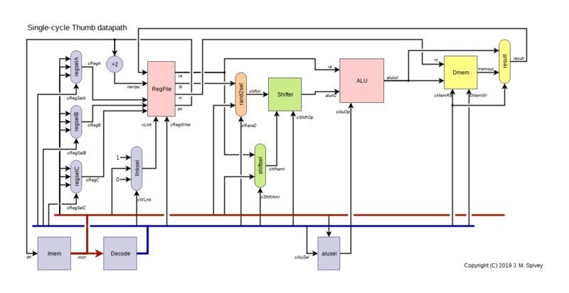
In order to implement the branch-and-link instructions bl and blx, we need one extra feature of the register file, and one small enhancement to the datapath. The register file has one further control input cLink that, when active, causes the nextpc value to be written to the link register LR, in addition to the normal updating of registers. This will permit us to implement an instruction that simultaneously sets the link register to a return address while loading the entry point of a subroutine into the PC.
Because the bx r and blx r instructions differ in only one bit, we need an extra multiplexer to derive this control signal, with three settings – 0 for most instructions, 1 for the bl2 instruction (see below), and a copy of instr<7> for these instructions.
The three values of the controlling cWLink control signal are denoted N, Y and C in the tables below.
Existing instructions are extended with cWLink = N, and the following rule covers the two branch-to-register instructions. The Ryy register selector denotes the four-bit field Instr<6:3>; high registers are allowed here, as in the familiar instruction bx lr.
| Instruction | opcode | cRegSelA |
cRegSelB |
cRegSelC |
cRand2 |
cShiftOp |
cShiftAmt |
cAluSel |
cMemRd | cMemWr | cRegWrite | cWLink |
|---|---|---|---|---|---|---|---|---|---|---|---|---|
bx/blx r |
01000:111 | - | Ryy |
Rpc |
RegB |
Lsl |
Sh0 |
Mov |
F |
F |
T |
C
|
As hinted in an earlier problem sheet, the 32-bit bl instruction can, in simple cases, be executed in two halves that we shall call bl1 and bl2.
The first half starts with bits 11110, and the second half starts with 11111, provided we assume bits J1 and J2 are both 1, as traditionally they were: only very long branches will make them anything else. We will implement the bl1 instruction by adding the offset, scaled appropriately, to the PC and putting the result in LR; then we implement bl2 by adding the second half of the offset to the LR, and putting the result in the PC, simultaneously setting LR to the return address.
| Instruction | opcode | cRegSelA |
cRegSelB |
cRegSelC |
cRand2 |
cShiftOp |
cShiftAmt |
cAluSel |
cMemRd | cMemWr | cRegWrite | cWLink |
|---|---|---|---|---|---|---|---|---|---|---|---|---|
bl1 |
11110 | Rpc |
- | Rlr |
SImm11 |
Lsl |
Sh12 |
Add |
F |
F |
T |
N
|
bl2 |
11111 | Rlr |
- | Rpc |
Imm11 |
Lsl |
Sh1 |
Add |
F |
F |
T |
Y
|
Stage 9: Conditional execution
There are several features of the Thumb instruction set that we're not going to implement, but one remains that is essential to writing working programs, and that is the mechanism for conditional branches: arithmetic instructions set the status bits NZCV, and there is a form of branch instruction that contains one of 14 conditions defined as logical combinations of the status bits.
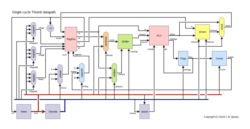
Our approach to implementing conditional branches will be to use the ALU to compute the target address of the branch from the PC value and the displacement, but to make the writing of the result into the PC conditional on the test being passed. Three new datapath elements and two new control signals will be needed. There is a small, 4-bit register to hold the NZCV flags, and a control signal that determines whether the flags are updated by each instruction. A separate, combinational circuit takes the register contents and the four-bit condition field shown in the instruction format, and computes a signal enable that indicates whether the condition is satisfied. (As usual, this circuit functions in every instruction, whether it is a conditional branch or not, and produces a nonsense output except when a conditional branch is in progress.)
The decision whether to write the result of an instruction back to a register becomes a dynamic one: in place of the signal cRegWrite appearing in the decoding table, there is a signal cWReg that takes values Y, N and C, with C denoting that the cRegWrite signal is taken from cEnabled.
We can add the new signals to the table for existing instructions: cWFlags indicates whether the instruction should write the flags or not: T for adds and lsls and all the other arithmetic and logical instructions, F for loads and stores and branches. The values T and F for cRegWrite are replaced by values Y and N for cWReg, with C used only in the following rule for conditional branch instructions.
| Instruction | opcode | cRegSelA |
cRegSelB |
cRegSelC |
cRand2 |
cShiftOp |
cShiftAmt |
cAluSel |
cMemRd | cMemWr | cWFlags | cWReg | cWLink |
|---|---|---|---|---|---|---|---|---|---|---|---|---|---|
b<c> |
11010 11011 |
Rpc |
- | Rpc |
SImm8 |
Lsl |
Sh1 |
Add |
F |
F |
F |
C |
N
|
cmp ri |
00101 | Rw |
- | - | Imm8 |
Lsl |
Sh0 |
Sub |
F |
F |
T |
N |
N
|
subs ri |
00111 | Rw |
- | Rw |
Imm8 |
Lsl |
Sh0 |
Sub |
F |
F |
T |
Y |
N
|
For comparison, the rules for subs ri and cmp ri are also given here: the only difference between them is that after the subtraction is performed, the subs instruction writes a register as well as updating the flags, and the cmp instruction just updates the flags.
It's important to note that conditional branches read but don't destroy the flags: that makes it possible to have one compare instruction followed by several branches conditional on its result:
    cmp r1, #0
    beq zero
    bgt positive
negative:
    ...
Context
None of the detail here really matters, except as an illustration of the challenges faced by a datapath designer. The hardware, once designed, is fixed, and must be designed so that, with appropriate settings of the control signals, every machine language instruction can be implemented. For a single-cycle design like this one, where each instruction takes exactly one clock cycle, the instruction decoder essentially expands each instruction into a long string of control bits, reversing a kind of compression that makes some useful operations expressible in the limited number of instruction bits, and others not expressible at all.
Summary of control signals
We can distinguish between decoded signals, which are determined by the opcode as looked up in the ROM, and therefore the same for all instances of an instruction, derived signals, which are the same for every execution of a particular instruction, and dynamic signals, which will differ from one execution of an instruction to the next.
| Decoded | Derived | Dynamic | Description |
|---|---|---|---|
pc |
Program counter value | ||
instr |
The 16-bit instruction | ||
cRegSelA, cRegSelB, cRegSelC |
Three rules for selecting registers | ||
cRegA, cRegB, cRegC |
The three register numbers | ||
ra, rb, rc |
The contents of the three registers | ||
nextpc |
Address of the next instruction | ||
cRand2 |
Rule for selecting shifter input | ||
shiftin |
Input to the shifter | ||
cShiftOp |
Shift operation | ||
cShiftAmt |
Rule for determining shift amount | ||
shiftamt |
Amount of shift | ||
aluin2, shcarry |
Outputs from the shifter | ||
cAluSel |
Rule for determining ALU operations | ||
cAluOp |
The ALU operation | ||
aluout, newflags |
Outputs from the ALU | ||
cMemRd, cMemWr |
Whether to read or write the memory | ||
memout |
Result of memory read | ||
result |
Result for write-back | ||
cWFlags |
Whether to update the flags | ||
cCond |
Condition to test | ||
enable |
Whether the condition is satisfied | ||
cWReg |
Rule for writing result register | ||
regwrite |
Whether result will be written | ||
cWLink |
Rule for updating link register | ||
cLink |
Whether link register will updated |
Questions
What's the difference between decoded, derived and dynamic signals?
Decoded signals are those that appear in the decoding tables and are determined by the instruction's opcode; derived signals also depend on other parts of the instruction halfword, and dynamic signals depend on other parts of the machine state.
- The decoded signals will be the same in every instance of an instruction – that it to say, two instructions that share the same opcode will have the same decoded signals. Note, however, that two instructions like
mov randmov i8may share the same mnemonic in assembly language, but have different opcodes, and so be treated as different instructions by the hardware, with different decoded signals. In the simulator, these decoded signals form the members of theControlstructurectrlcontained in one of the decoding tables, and have names likectrl->cShiftAmt. - The derived signals will be the same whenever a particular instruction is executed, because they are determined by the bits of the instruction taken all together; for example, the instruction
add r3, r1, r2always writes its result to registerr3, and so hascRegC = 3. In the simulator, these derived signals are outside theControlstructure, but also have names likecRegCthat start with a lower-casecfollowed by an upper-case letter. - The dynamic signals differ from one execution of the instruction to another, so that at one time that
addinstruction could write 7 tor3, and another time it could write 8, and the value of theresultsignal would be different in the two cases.
In the lectures, you talk about processor designs containing lots of multiplexers, but some books talk about designs containing various busses. What's the difference?
There isn't really a difference: a bus in a conventional design is a bundle of wires that can be driven by several sources at different times, usually by setting one source to produce an output and the others to enter a high-impedance state. If there is a difference, it is that we are neutral about the technology used to implement a multiplexer – logic gates, or the kind of three-state logic just described – whereas a bus, especially if it stretches between chips, has a specific implementation that must be followed.


